Architectural Constructability Vignettes
Throughout my architecture career I have produced myriads of sketches examining constructability or studying details of an architectural design solution on around one hundred projects. The practice is an outcropping of my architectural rendering experience, constant since the very first days of my internship. Most of these drawings are ephemeral despite their beauty. Rather than being objects of artistic expression, these drawings are communication tools intended to resolve contradictions or conflicts in documentation, answer questions from the field, or explain planned conditions to the Owner. The sketches demonstrate an innate skill in visualizing construction conditions. Despite the fact the drawings are not aided by computers, they are rather faithful to scale and depth in an age before the easy availability of computer modeling. As the field entered the computer modeling era, I was particularly well prepared. My innate skills framed directly into the mentality of digitally modeling construction.
The drawings normally facilitated communication among the architect (including myself), the design team (civil, structural, and MEP engineers), the Owner via the designated representative, and the contractor and subcontractors. They were effective, legible, clear tools in resolving conflict or obtaining an approved remedy. I applied this methodology widely across all my projects; these happened to be saved. Shortly after these sketches I began keeping project sketchbooks, especially for items I designed or detailed. One of these is in possession but is misplaced; it features taqga-reneya dimensioning. Once it is located it will be scanned and the drawings will be visible here.
The method of studying details through these sort of constructability sketches has largely been replaced by digital modeling. These drawings represent an early stage of construction detail visualization that is now handled by digital vignettes.
 |
 |
 |
 |
|
k6331
Running Track Steel Study
This drawing sorts out a steel fabrication drawing to ensure it jives with the design. |
k635a
CMU vs Steel Pan Stair Study
Three options to handle CMU suspended over a steel stringer. |
k63a3
Face Brick-Metal Panel Transition Study
Drawing explores the junction of three exterior wall types. |
k63a7a
Lobby-Natatorium Study
Study of the interface of lobby and natatorium construction. |
 |
 |
 |
 |
|
k63a7b
CMU Thickness Transition Study
Drawing serves to explain the effect of changing masonry wall thickness. |
k63a7c
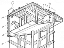
Parapet-Canopy Study
Examination of the construction of a parapet and canopy. |
k63a7d
Hollow-Core Plank Rail Study
1
One option for a rail atop a steel channel fascia-stringer. |
k63a7e
Hollow-Core Plank Rail Study 2
A second option for a rail atop a steel tube fascia-stringer. |
 |
 |
 |
 |
|
k63a8a
Fitness Center MEP Study
This simple sketch conveys requirements from the MEP engineer to the head design architect. |
k63a8b
Fitness Center Architectural Concept Study
Explanation of the architectural concept to the Owner and other members of the design-construction team. |
k63a8e
Lobby Atrium Exterior Study
Study of the exterior of the atrium, involving curtainwall, metal panel, and masonry, intended to verify intent. |
k63a8f
Lobby Atrium Interior Study
Examination of the interior of the lobby roof showing structural steel, decking, and light gauge framing, intended to verify conditions with the design team and Owner. |
 |
 |
 |
 |
|
k63a8g
Lobby Roof Framing Study
Study of the light gauge framing associated with the brow outside of the atrium clerestory. |
k63b8a
Wall Simplification Option 1
The first of three options attempting to iron out inconsistencies and reduce cost in a rear wall using a mixed framing approach. |
k63b8b
Wall Simplification Option 2
The second of three options attempting to iron out inconsistencies and reduce cost in a rear wall using masonry backup for the entire wall. |
k63b8c
Wall Simplification Option 3
The third of three options attempting to iron out inconsistencies and reduce cost in a rear wall, using light gauge steel framing for the entire wall. |
 |
 |
|
|
|
k6692
Civil Survey Property Line Study
Simple study that attempts to convey facts about the property line to the Owner and design team. |
k66a1
Benchmark Accord Study
Drawing intended to achieve accord among the design team and builder regarding the project benchmark. |
|
|
This page last modified Monday 16 April 2012.


